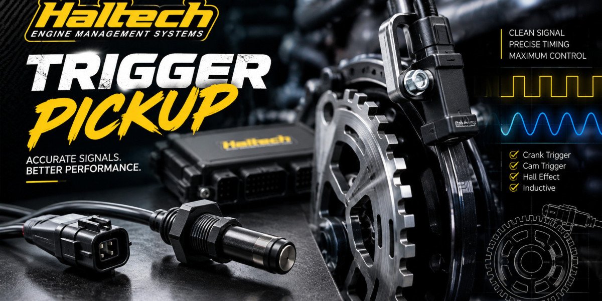

An engine is a rotating machine and everything it does depends on timing. Fuel must be injected while the right valve is open. Spark must arrive just before the piston reaches the point of peak pressure. To manage this, the ECU needs a continuous, accurate description of where the engine is in its cycle. That description comes from the crankshaft position sensor, the device many tuners call a haltech trigger pickup position sensor when it is paired with a Haltech ECU.This article looks at the principles behind crankshaft position detection: how a tooth becomes a voltage, how the ECU turns pulses into angles, how it separates one engine cycle from the next and what can go wrong. If you understand the theory, installation, diagnosis and tuning all become easier.
The Core Concept Turning Rotation Into a Signal
A crankshaft rotates smoothly, but the ECU is a digital device. It needs discrete events to count. A toothed wheel on the crank provides those events. As each tooth passes a stationary sensor, the sensor produces a pulse and the ECU measures the time between pulses.
From this, the ECU derives two things
Engine speed. Pulses per unit of time give rpm. This is how the system functions as an engine speed monitoring sensor and supplies the RPM axis for fuel and ignition tables.
Engine position. The pattern of teeth identifies particular crank angles, which are the basis of crank angle sensing.
The wheel's tooth pattern therefore acts as a ruler. Evenly spaced teeth give the ECU fine angular resolution and a deliberate irregularity gives it a landmark.
Missing Teeth, Gaps and Landmarks
A wheel with evenly spaced teeth alone cannot tell the ECU which revolution it is on or which tooth is which. To solve this, designers remove one or two teeth, or add extra ones, creating a recognisable gap in the sequence.
In a 36-1 pattern, there are 36 tooth positions with one missing. The ECU sees the gap as a longer time between pulses and identifies it as a reference point. In a 60-2 pattern, two adjacent teeth are removed. Each pattern has trade-offs. More teeth give finer resolution and faster correction of speed variation, while fewer teeth are easier to decode at low speeds and generate fewer pulses at high rpm.Because the ECU recognises the gap by comparing time intervals, it assumes the engine is not accelerating or decelerating abruptly in that moment. This is part of why a clean, repeatable signal matters so much. Noise that looks like an extra tooth, or a missed pulse, can make the ECU misidentify the gap and lose its position.
Crank Signal Versus Cam Signal
A four-stroke engine takes two crankshaft revolutions to complete one cycle. The crank sensor alone cannot distinguish the compression revolution from the exhaust revolution, because the wheel looks identical in both. To resolve this, many systems add a camshaft position sensor, which turns once per cycle.
The cam signal, often called the home or phase signal, tells the ECU which of the two crank revolutions is in progress. This enables full sequential injection and individual coil control. Without a cam signal, many setups use wasted-spark ignition and grouped or batch injection. Both approaches are valid and the choice depends on the engine and the goals.Together, the crank and cam inputs create the engine synchronization signal that the ECU needs for full control. This process, ECU engine synchronization, takes place in the first fraction of a second of cranking. The ECU gathers pulses, identifies the gap, confirms the cam phase and then declares sync, after which it begins to fire injectors and coils.
How a Variable Reluctance Sensor Generates a Signal
A variable reluctance sensor consists of a permanent magnet with a pole piece, surrounded by a fine coil. The magnet creates a magnetic field that extends into the space in front of the sensor tip. When a steel tooth moves into that field, it changes the magnetic flux through the coil. Faraday's law tells us that a changing flux induces a voltage.
As the tooth approaches, the flux increases and the coil produces a voltage of one polarity. As the tooth leaves, the flux decreases and the polarity reverses. The result is an alternating waveform, with a zero crossing near the tooth centre.
Two important consequences follow
Amplitude depends on speed. A faster-moving tooth changes the flux more quickly, so the voltage rises with rpm. At cranking speed, it is small. At high rpm, it can reach many volts, which is why ECU input circuits include protection and conditioning.
The ECU detects a crossing or threshold. The input circuit converts the analogue waveform into a digital edge. Because the precise point where this conversion occurs affects timing, the sensor gap and wiring must be consistent.
This is why a Haltech magnetic trigger sensor or reluctor trigger sensor needs careful setup, yet remains popular for its simplicity and tolerance of hostile environments.
How a Hall Effect Sensor Generates a Signal
A Hall effect sensor contains a semiconductor element through which a small current flows. When a magnetic field passes through it perpendicular to the current, a small voltage develops across the element. Onboard electronics amplify this voltage and switch an output transistor on or off at a defined threshold.
Because the sensor has active electronics, it requires a supply and produces a clean digital output whose amplitude is independent of speed. It can detect a tooth even at zero speed, which is a clear advantage for starting and for engines with very low cranking speeds.Some Hall sensors contain their own biasing magnet and detect ferrous teeth, while others detect a magnet embedded in or attached to the rotating target. Using the wrong combination of sensor and target leads to a weak or absent signal.
The Role of the Air Gap in Signal Quality
The gap between the sensor and the teeth shapes the signal. In a VR sensor, a larger gap weakens the magnetic coupling and reduces output amplitude. A trigger sensor air gap that is too large can make the signal fall below the ECU's detection threshold at cranking speed. A gap that is too small can cause overly strong signals at high rpm and risks contact if the wheel has runout.In a Hall sensor, the effect is different, but a gap beyond the sensor's specification will cause missed detections. In both cases, the manufacturer's figure should be followed and the gap checked at the point of tightest clearance.
Signal Conditioning Inside the ECU
The Haltech ECU trigger sensor input is not a simple wire into a processor. It includes protection against over-voltage, filtering to remove high-frequency noise and a comparator or similar circuit that converts the signal into clean digital edges. On inputs that support both VR and Hall sensors, the software setting changes how the input is biased and how thresholds are applied.
This is the reason the sensor type setting in the software must match the hardware. Configuring a VR input for a Hall sensor, or the reverse, can produce unreliable detection or none at all. Consult the documentation for your specific Haltech Elite ECU or Haltech Nexus ECU model to see which inputs support which types.
From Edges to Angles How the ECU Calculates Timing
Once the ECU has a stream of clean edges and has identified the reference point, it computes crank angle. Suppose a 36-1 wheel gives a nominal 10 degrees between teeth. The ECU knows that a certain number of teeth after the gap, the piston of cylinder one reaches top dead centre. It then predicts the time to the next tooth and uses that to schedule events between teeth.
This prediction is the basis of ignition timing control. For example, to fire at 25 degrees before top dead centre, the ECU waits for a particular tooth and then delays a calculated time. At varying engine speeds, that time changes and the ECU recalculates it each cycle. If the signal contains jitter, the prediction is unstable and the actual timing wanders.The trigger offset or trigger angle, set during calibration, links the electronic reference to the physical top dead centre. This is why a timing light check is essential: the ECU can count teeth perfectly but still be offset from true timing.
Where Signal Problems Come From
Understanding the sensing principle helps identify faults. Common causes include
Electrical noise. Ignition coils and high-current wiring induce voltages in nearby sensor cables, particularly VR circuits. Shielding, twisting and routing reduce the effect.
Mechanical issues. A loose or eccentric wheel, a flexing bracket or damaged teeth produce irregular pulses.
Gap errors. An incorrect gap leads to weak or distorted signals.
Connection faults. High resistance or intermittent contact in a plug or crimp mimics noise or missed teeth.
Wrong configuration. Incorrect pattern, edge polarity or sensor type causes failure even with a perfect signal.
Connection integrity deserves special attention because it is easy to overlook. A quality sealed connector from a motorsport range, such as the ASDD41-WAYFLGSKTN-KEYRED, helps keep low-level sensor signals stable by providing consistent contact pressure and environmental sealing across a large number of circuits.
Trigger Wheels in Motorsport Applications
In motorsport engine sensor applications, the environment is more severe. Higher rpm reduces the time between teeth, so the sensor and ECU must respond quickly. Vibration is higher and temperatures are more extreme. A crank trigger system designed for competition therefore tends to use precision-machined wheels, rigid brackets, sealed sensors and robust connectors.
Some builders use a wheel mounted on the front of the crank, others on the flywheel or on a dedicated shaft. Each has advantages. A front-mounted wheel can be affected by crank torsional vibration, which makes the tooth timing appear to oscillate. A flywheel-mounted wheel sits closer to the point of torque delivery and can be more stable, but access and packaging may be harder.
Crank Signal Quality and Engine Protection
A good crank signal does more than permit starting. It underpins many protective strategies. Rev limiting depends on accurate rpm. Knock control relies on knowing the crank angle at which events occur. Boost control, launch control and traction strategies all use engine speed. If the signal is noisy, a rev limit may trigger early, or fail to trigger at all.For this reason, experienced tuners monitor sync status and any trigger error counters during logging sessions. An occasional error count can be an early warning of a developing wiring or mounting problem, long before it becomes a no-start.
Planning the Electrical System Around the Sensor
When designing a full engine harness, group the low-level sensor circuits and keep them separate from high-current wiring. Place the crank and cam sensor lines in a shielded bundle and terminate shields at the ECU. Use sealed, locking connectors with proper strain relief. For harnesses that combine many sensors in one plug, a larger connector such as the 41-way plug and socket family in the ASDD series allows a compact layout that is easy to service.A neat, well planned loom is not only about appearance. It reduces noise coupling, simplifies diagnosis and helps ensure the trigger signal reaches the ECU as it leaves the sensor.
Conclusion
The Haltech crankshaft position sensor is the starting point of the engine management chain. It converts the physical rotation of a toothed wheel into pulses, the ECU turns those pulses into speed and angle and everything else, from injection to ignition and protection, builds on that foundation. Whether you use a VR or Hall sensor, what matters is the full system a true wheel, a rigid bracket, the right gap, quality shielded wiring, sealed connectors and correct ECU configuration.By understanding how the signal is created and interpreted, you can diagnose faults faster and build more reliable engines. When you are ready to source connectors and wiring supplies for your project, explore the full range at Arctic Performance Parts.
Frequently Asked Questions (FAQs)
What is the difference between a crank sensor and a cam sensor?
The crank sensor reads the crankshaft wheel and provides engine speed and position. The cam sensor turns once per cycle and tells the ECU which crank revolution is in progress, enabling sequential control.
Why does a VR sensor signal get stronger at higher rpm?
Because the induced voltage depends on how fast the magnetic flux changes. A faster-moving tooth produces a larger voltage.
Can an ECU run without a cam sensor?
Often yes. Many setups use a crank-only signal with wasted-spark ignition and batch injection, although sequential control needs a cam or phase input.
What does a missing tooth do?
It creates a unique gap the ECU can recognise as a reference point, allowing it to identify absolute crank position.
How do I know if my trigger signal is clean?
Use the ECU's trigger diagnostics or an oscilloscope. A clean signal has consistent amplitude or square edges, one clear gap per revolution and no stray pulses.